美国混凝土结构规范ACI318-19关于特殊结构墙的设计和构造均有重大修改和更新,本文尝试去理解和学习美国规范的一些特色观点。
2019年版《美国混凝土建筑结构规范》(ACI 318-19)对特殊结构墙的设计和构造要求进行了较大修改。根据《美国荷载规范》ASCE/SEI 7-16规定,抗震设计类别为D、E、或 F的剪力墙结构、框架结构和双重抗侧体系均需要设置特殊结构墙( special structural walls)。这些对设计和构造要求的修订(详见 ACI 318 第18.2.6 和 18.10节),概括起来有以下几点:
(1)引入 80 级和 100 级变形钢筋,以抵抗弯矩、轴力和弯矩组合作用、剪切作用;
(2)对纵向钢筋端部连接和拼接位置的新要求;
(3)细长墙肢边缘构件纵筋最小配筋面积的新要求;
(4)放大细长墙肢的设计剪力。
(5)对墙肢的变形和侧移能力的新要求。
(6)墙肢边缘构件和腹板内水平钢筋构造的修订。
(7)墙肢边缘构件中箍筋最大间距的要求。
1 高强度钢筋的应用
经过大量的研究和探索,更高强度的钢筋(屈服强度为80 000psi和10 000psi)在特殊结构墙等钢筋混凝土结构中的应用成为了可能。对于特殊结构墙,ASTM A706 80 级和 100 级变形钢筋被用来抵抗弯矩、轴力以及弯曲和轴向力的组合作用,也被用来抵抗剪切作用。
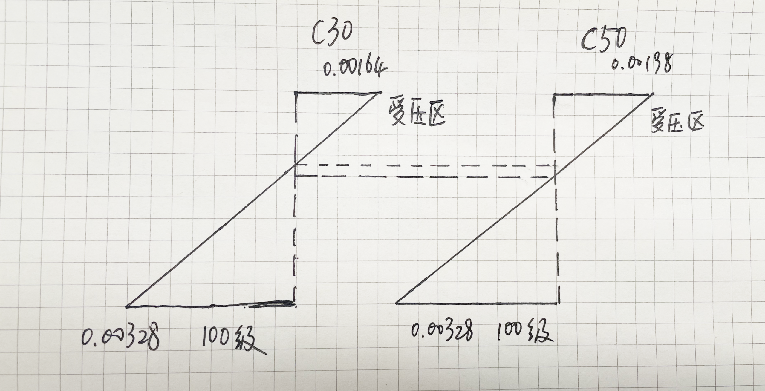
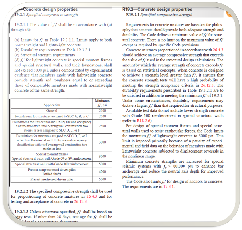
根据 ACI 318 第 19.2.1.1条,对于具有 60 级或 80 级钢筋的特殊结构墙,混凝土抗压强度f ‘c不低于 3,000 psi;对于配置 100 级钢筋的墙肢,f’ c* 不低于5,000psi。配置100级高强钢筋的特殊结构墙,混凝土受压强度越高,钢筋锚固越好,中性轴下移,从而提高了整体性能。
我国《混凝土结构通用规范》(GB55008-2021)开始采用HRB500等高强钢筋,同时也提高了最低混凝土强度的要求,大概也是相同的道理。
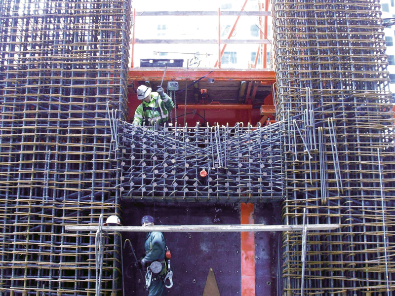
在特殊结构墙中使用高强度钢筋,相比采用60级钢筋会采用更少数量的钢筋,这将会更方便浇筑混凝土,特别是在剪力墙的连梁中,不仅可以节约绑扎钢筋浇筑混凝土时间,还能提高现场浇筑的便利性和密实度。
2 对纵筋截断和搭接位置的新要求
ACI 318-19第18.10.2.3规定了特殊结构墙纵筋截断和搭接位置的新要求,见下图。
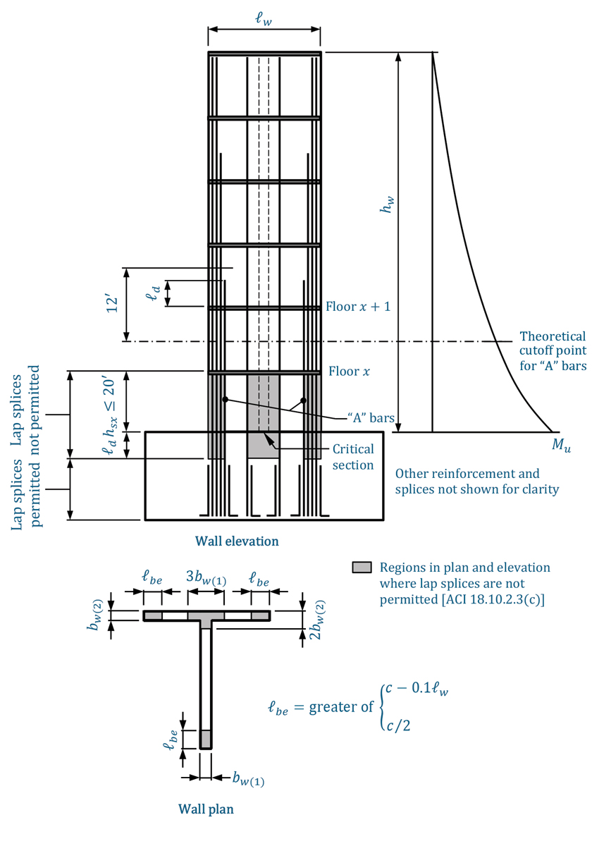
上图介绍了纵筋截断的要求。除了顶部之外,墙体纵筋必须在理论截断位置上方至少延伸 12 英尺 (3657.6mm),但不必延伸超过上一层楼面以上受拉长度 ,可以根据 ACI 318-19第25.4.2.3 或 25.4.2.4条确定。
对于侧向荷载作用下,在剪力墙底部可能发生屈服的部位,必须乘以 1.25,因为 :(1) 钢筋实际屈服强度超过设计屈服强度 的可能性; (2) 应变硬化和循环荷载的影响。与之前版本的要求相比,将纵延伸至上一层以上长度,是一种更实用的措施。
对于剪力墙约束边缘构件,纵筋底部搭接位置不允许高出临界截面(Critical section,钢筋因侧向位移屈服部位截面) 以上大于层高 的距离,也不允许低于临界截面以下的距离,其中不应超过 20 英尺。上图中可知,ACI318-19还规定了约束边缘构件的长度。大量试验结果表明,当搭接接头位于或靠近临界截面时,特殊结构墙的非弹性变形能力显著降低。
3 边缘构件最小配筋面积的规定
ACI318-19还规定了墙肢边缘构件以及细长结构墙(高跨比 大于或等于 2)的最小配筋面积,从结构底部到墙的顶部,按承受轴力和弯矩的临界截面进行设计。 根据 ACI 318第18.10.2.4条,边缘构件最小长度取
  ,并且墙厚不低于
 。
。
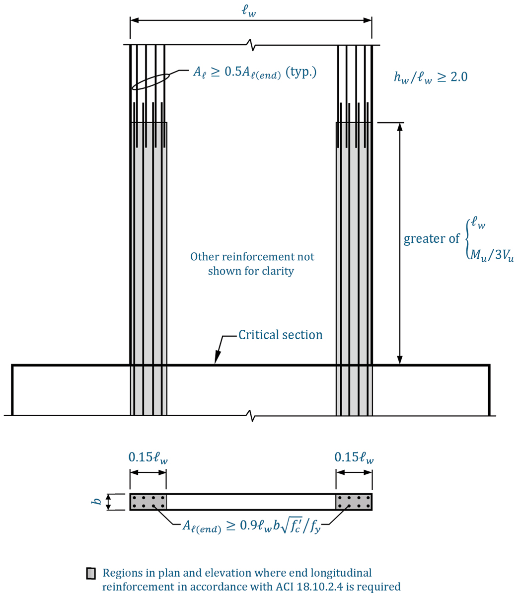
上图所示的要求,旨在使得剪力墙底部塑性铰区形成分布良好的二次弯曲裂缝,从而降低这些位置钢筋断裂的可能性。临界截面到搭接位置最小距离应为 和
和 中的较大者。其中,
 和
和 分别是临界截面的弯矩和剪力。为了避免在塑性铰区附近形成薄弱截面,仅不超过50%的纵筋被允许在墙的任意位置截断。
4 放大设计剪力
在 ACI 318-19之前版本中,特殊结构墙的抗剪承载力是根据 《美国荷载规范》ASCE-7中规定的地震荷载对结构进行弹性分析得到的最大剪力,这与基于能力设计法(Capacity design) 得到的特殊弯矩框架中的梁、柱和节点的要求不匹配的。此外,由于实际的地震作用中,剪力可能比使用 ASCE/SEI 7 载荷获得的剪力大得多。因此,2019 年之前 ACI 318 中对特殊结构墙的抗剪设计要求并不能确保在临界截面剪切破坏之前发生延性弯曲屈服。
ACI 318-19 中引入了新抗剪设计要求来解决这些问题。特殊结构墙的设计剪力 必须按 ACI 318式18.10.3.1计算。
![\[V_{e}=\Omega_{v} \omega_{v} V_{u} \leq 3 V_{u}\]](http://www.structurevspoem.com/wp-content/ql-cache/quicklatex.com-9e9554a67e7131ed30eea16b48b3846c_l3.png "Rendered by QuickLaTeX.com")
在上式中, 是超强系数,对于高长比
 等于
等于 和 1.5 中的较大者;对于高长比
 的墙,
的墙, 。
。 是临界截面上方整个结构墙的高度。当
 ,
, 。选择 1.5 的值是因为在结构墙中配置的纵筋数量(对
 有直接影响)通常大于计算需求的数量。
假定纵筋中的应力等于 1.25 f y并且强度折减系数φ等于 1.0,则墙肢可能抗弯强度 根据临界截面处的墙体特性确定的。临界截面处的折减弯矩是根据 《美国荷载规范》ASCE-7对结构进行弹性分析得到。因为和取决于临界截面的轴力,所以必须使用产生最大值条件来确定
 。
。
对于 的墙,动力放大因子
 由 ACI 318 式(18.10.3.1.3)得到 :
 是临界截面以上楼层数,不得小于
 ,这个限值是来考虑层高较大的建筑物。
对于 的墙,
的墙, 。
。
动力放大因子考虑了多层建筑多模态的响应。考虑到高阶模态可以使侧向力的质心向下移动,从而增加临界截面的剪力。
其中由 ACI 318 式(18.10.3.1)得到,在确定细长特殊结构墙的设计抗剪强度 时,取
时,取 。的确定,除了超强系数和动力放大因子外,还必须根据ASCE-7 第 12.3.4.2 条考虑冗余度ρ。很明显,可以大于(高达 3 倍),这很可能需要更厚的墙厚或配置更多抗剪钢筋。
5 对墙肢侧移能力的新要求
根据 ACI 318 -19第18.10.6.2条,设置有边缘约束构件的细长特殊结构墙 (),必须满足新的侧移能力要求。
 (2)
(2)
 (3)
(3)
在这些方程中, = 墙顶的位移能力;
 = 墙体受压面的宽度;
 = 根据墙顶部的设计位移
 方向一致的轴力和弯矩计算得到的中性轴高度;
 = 墙腹的总面积减去开洞面积。
 表示侧移能力,不小于0.015,表
 示侧移需求。满足这种侧移能力要求则表示设计地震作用下结构损坏的风险较小。对于没有翼缘的墙,等于墙的厚度。如果随变化,例如带有翼缘的墙应使用的平均值,参考 ACI 318 第 18.10.5.2 节中定义的有效翼缘宽度。当
 且
且  时,可以从式(2)推导得到式(2)。
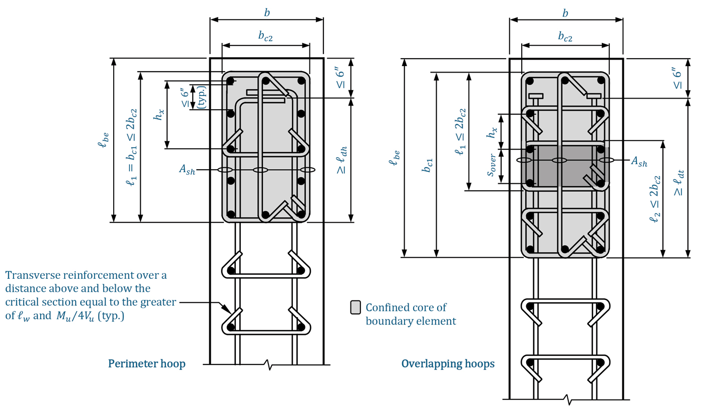
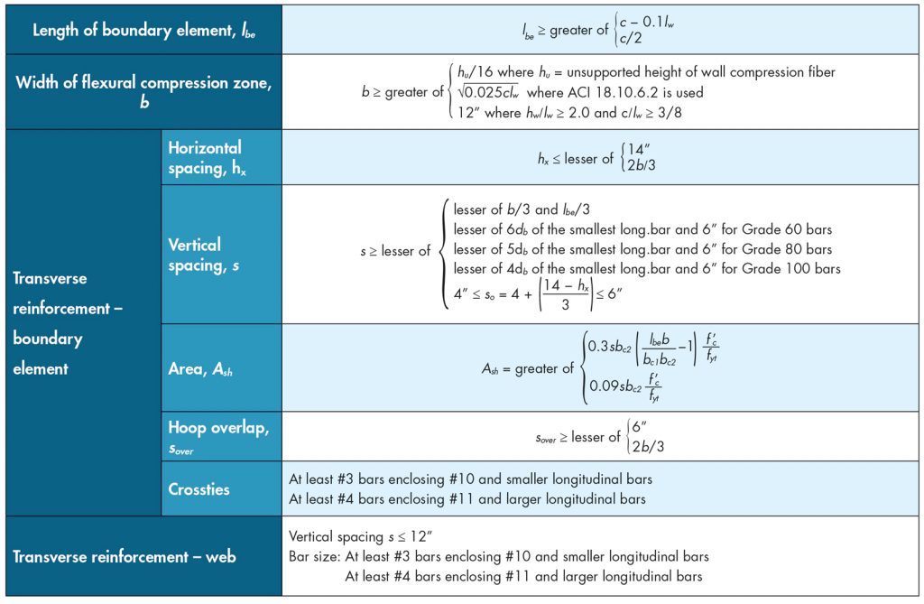
6 构造要求
针对特殊结构墙,ACI318-19引入和修订了一些构造,具体可以参考第 18.10.6.4 和 18.10.6.5 条。主要修订如下:
- 对约束边缘构件的水平筋间距限值进行了修订,包括在预期屈服区域内外的 80 级和 100 级水平钢筋最大竖向间距限值。
- 规定了约束边缘构件的箍筋单肢的长度限值。如果无法满足此限值,则必须使用相邻的重叠箍,重叠长度至少为 6 英寸和边缘构件厚度的三分之二,取两者中的较小值。
- 腹板竖向钢筋必须有侧向支撑,由角部或两端带有弯钩的水平筋提供,距离临界截面的上下距离至少为 和
 中的较大者。
参考文献
ACI (American Concrete Institute). 2019. Building Code Requirements for Structural Concrete and Commentary. ACI 318-19, Farmington Hills, Michigan.
American Society of Civil Engineers (ASCE). 2017. Minimum Design Loads and Associated Criteria for Buildings and Other Structures, ASCE/SEI 7-16, Reston, VA.
SEAOC Seismology Committee. 2019. “Reinforced Concrete Structures.” The SEAOC Blue Book: Seismic Design Recommendations, Structural Engineers Association of California, Sacramento, CA.
————————————————————————————————————————————————————————————————————————————————
The 2019 edition of the American Concrete Institute (ACI) 318-19 code has introduced significant revisions and updates to the design and construction requirements for special structural walls. This article aims to understand and explore some of the distinctive perspectives of the American code.
The 2019 edition of the Building Code Requirements for Structural Concrete (ACI 318-19) has introduced substantial changes to the design and construction requirements for special structural walls. According to ASCE/SEI 7-16 Minimum Design Loads for Buildings and Other Structures, shear walls, frame systems, and dual lateral force-resisting systems assigned to Seismic Design Categories D, E, or F must incorporate special structural walls. These revised provisions (see ACI 318 Sections 18.2.6 and 18.10) can be summarized as follows:
- Introduction of Grade 80 and Grade 100 deformed reinforcement to resist flexure, axial load and their combinations, and shear forces;
- New requirements for longitudinal reinforcement cutoff and splice locations;
- Updated minimum longitudinal reinforcement area requirements for boundary elements in slender wall segments;
- Amplification of design shear forces for slender wall segments;
- New requirements for wall segment deformation and drift capacity;
- Revised detailing requirements for horizontal reinforcement within wall web and boundary elements;
- Maximum spacing requirements for transverse reinforcement (ties) in wall boundary elements.
1 Application of High-Strength Reinforcement
After extensive research and exploration, higher-strength reinforcing bars (with yield strengths of 80,000 psi and 100,000 psi) have become viable for use in reinforced concrete structures such as special structural walls. For special structural walls, ASTM A706 Grade 80 and Grade 100 deformed bars are used to resist bending moments, axial forces, combined bending and axial loads, and shear forces.
According to ACI 318 Section 19.2.1.1, for special structural walls with Grade 60 or Grade 80 reinforcement, the specified compressive strength of concrete, f’c, shall not be less than 3,000 psi; for walls with Grade 100 reinforcement, f’c shall not be less than 5,000 psi. Using high-strength Grade 100 reinforcement in special structural walls allows better anchorage due to higher concrete compressive strength, shifting the neutral axis downward and thus enhancing overall performance.
Strain and Stress Angle
China’s General Code for Concrete Structures (GB55008-2021) has begun adopting high-strength reinforcement such as HRB500 and also increased the minimum concrete strength requirements, following similar logic.
Original Text from ACI 318-19
Using high-strength reinforcement in special structural walls reduces the number of bars compared to Grade 60 steel, facilitating concrete placement. This is particularly beneficial in coupling beams, where reduced reinforcement improves construction efficiency and concrete consolidation.
Coupling Beam Construction Site
2 New Requirements for Longitudinal Bar Cutoff and Splice Locations
ACI 318-19 Section 18.10.2.3 introduces new requirements for longitudinal bar cutoff and splice locations in special structural walls, as shown in the figure below.
Longitudinal Bar Requirements for Special Structural Walls
The figure above illustrates the cutoff requirements for longitudinal bars. Except at the top, wall longitudinal bars must extend at least 12 inches (3657.6 mm) beyond the theoretical cutoff point but need not extend beyond the floor level above by more than the tension development length , which can be determined per ACI 318-19 Sections 25.4.2.3 or 25.4.2.4.
For regions where yielding may occur at the base of shear walls under lateral loads, must be multiplied by 1.25 due to:
(1) the possibility of actual steel yield strength exceeding the design value ;
(2) strain hardening and cyclic loading effects. Compared to previous editions, extending bars by above the upper floor level is a more practical measure.
For confined boundary elements in shear walls, splice locations must not be closer than below the critical section (the section where steel yields due to lateral displacement) nor more than one story height above it, where should not exceed 20 feet. As shown in the figure, ACI 318-19 also specifies the length of confined boundary elements. Experimental results show that if splices are located near the critical section, the inelastic deformation capacity of special structural walls is significantly reduced.
3 Minimum Reinforcement Area for Boundary Elements
ACI 318-19 also specifies minimum reinforcement area requirements for wall boundary elements and slender structural walls (aspect ratio  ) from the base to the top of the wall, designed for critical sections under axial load and bending moment. According to ACI 318 Section 18.10.2.4, the minimum boundary element length is , and the wall thickness must be at least
  .
.
Longitudinal Bar Requirements for Wall Boundary Elements
The requirements shown in the figure aim to promote distributed secondary flexural cracks at the base plastic hinge zone of shear walls, reducing the risk of steel fracture. The minimum distance from the critical section to the splice location should be the larger of and  , where and are the moment and shear at the critical section. To avoid weak sections near the plastic hinge zone, no more than 50% of longitudinal bars may be cutoff at any location in the wall.
4 Amplified Design Shear
Prior to ACI 318-19, the shear strength of special structural walls was based on the maximum shear force obtained from elastic analysis under seismic loads per ASCE-7. This approach was inconsistent with the capacity design method (Capacity design) used for beams, columns, and joints in special moment frames. Moreover, actual seismic shear forces often exceed those calculated using ASCE/SEI 7 loads. Thus, pre-2019 ACI 318 provisions did not ensure ductile flexural failure before shear failure at critical sections.
ACI 318-19 addresses these issues by introducing new shear design requirements. The design shear force for special structural walls must be calculated using ACI 318 Equation 18.10.3.1:
![\[V_{e} = \Omega_{v} \omega_{v} V_{u} \leq 3 V_{u}\]](http://www.structurevspoem.com/wp-content/ql-cache/quicklatex.com-737e6734a31a802af616f3b933a7d208_l3.png "Rendered by QuickLaTeX.com")
In this equation:
- is the overstrength factor. For walls with aspect ratio
 is the larger of
  and 1.5; for
  ,
,  .
. - is the height of the wall above the critical section.
- When
 ,
,  . The value 1.5 accounts for the fact that the number of longitudinal bars (which directly affects ) is typically greater than required.
Assuming steel stress equals  and strength reduction factor
  , the probable flexural strength is determined based on wall properties at the critical section. The reduced moment is obtained from elastic analysis per ASCE-7. Since and depend on axial force at the critical section, the condition producing the maximum must be used to determine .
For walls with  , the dynamic amplification factor
  is given by ACI 318 Equation (18.10.3.1.3):
![\[\omega_{v} = \begin{cases} 0.9 + \frac{n_s}{10}, & \text{if } n_s \leq 6 \\ 1.3 + \frac{n_s}{30} \leq 1.8, & \text{if } n_s > 6 \end{cases}\]” title=”Rendered by QuickLaTeX.com”></p>
<p>where <img loading=](http://www.structurevspoem.com/wp-content/ql-cache/quicklatex.com-191db7ff471119316278c1fb667744aa_l3.png "Rendered by QuickLaTeX.com") is the number of floors above the critical section, not less than , accounting for buildings with large story heights. For
is the number of floors above the critical section, not less than , accounting for buildings with large story heights. For  ,
,  .
.
The dynamic amplification factor considers multi-modal responses in multi-story buildings. Higher modes can shift lateral force centroids downward, increasing shear at the critical section.
The design shear strength for slender special structural walls uses  . In addition to the overstrength and dynamic factors, must account for redundancy
  per ASCE-7 Section 12.3.4.2. Notably, can exceed by up to 3 times, potentially requiring thicker walls or additional shear reinforcement.
5 New Requirements for Wall Drift Capacity
According to ACI 318-19 Section 18.10.6.2, slender special structural walls with confined boundary elements () must satisfy new drift capacity requirements:
![\[\frac{\delta_c}{h_{wcs}} = \frac{1}{100}\left(4 - \frac{1}{50}\left(\frac{\ell_w}{b}\right)\left(\frac{c}{b}\right) - \frac{V_e}{8\sqrt{f'_c}A_{cv}}\right) \geq \frac{1.5\delta_u}{h_{wcs}} \quad \text{(2)}\]](http://www.structurevspoem.com/wp-content/ql-cache/quicklatex.com-b0cb8d6df54183c535acc3f186fbfee6_l3.png "Rendered by QuickLaTeX.com")
![\[b \geq \sqrt{0.025 \ell_w c} \quad \text{(3)}\]](http://www.structurevspoem.com/wp-content/ql-cache/quicklatex.com-25aceee4f279408bb2ed381f633bd340_l3.png "Rendered by QuickLaTeX.com")
In these equations:
 = displacement capacity at wall top;
 - = width of compressed face;
- = neutral axis depth calculated using axial force and moment at design displacement
 ;
; - = gross web area minus openings.
 represents drift capacity, which must be at least 0.015. For walls without flanges, equals wall thickness. If varies (e.g., flanged walls), use the average value per ACI 318 Section 18.10.5.2. Equation (2) ensures low seismic damage risk if satisfied.
6 Detailing Requirements
ACI 318-19 introduces revised detailing requirements for special structural walls (see Sections 18.10.6.4 and 18.10.6.5), including:
- Revised maximum spacing limits for horizontal reinforcement in boundary elements, including 80- and 100-grade steel in expected yielding zones;
- Maximum single-leg tie length limits for boundary elements. If limits are not met, overlapping ties with at least 6 inches overlap and two-thirds of boundary thickness (whichever is smaller) are required;
- Vertical web reinforcement must be laterally supported by hooked or corner horizontal bars, with a minimum distance of the larger of and
 from the critical section.
Detailing Requirements for Wall Boundary Elements
Detailing Requirements for Wall Boundary Elements
References
- ACI (American Concrete Institute). 2019. Building Code Requirements for Structural Concrete and Commentary. ACI 318-19, Farmington Hills, Michigan.
- American Society of Civil Engineers (ASCE). 2017. Minimum Design Loads and Associated Criteria for Buildings and Other Structures, ASCE/SEI 7-16, Reston, VA.
- SEAOC Seismology Committee. 2019. “Reinforced Concrete Structures.” The SEAOC Blue Book: Seismic Design Recommendations, Structural Engineers Association of California, Sacramento, CA.