This is the 28th original article of this code. Creating original content is challenging, so please appreciate it while reading.
Last time, we elaborated on Python – driven Abaqus Solid Finite Element Modeling [with Source Code], which received numerous likes and attention from many friends. For instance, the following friend offered encouragement backstage in a rather showy manner, which greatly inspired this code. This code is also gradually cultivating its official account. I would like to express my gratitude to fellow professionals for their support and comments. This code will continue to work hard! Beyond technology, this code may convey more passion for the industry and some learning methods for new technologies.
Figure | A showy encouragement from a fellow professional
As mentioned last time, utilizing Python scripts during the modeling process can simplify tedious modeling tasks. However, the issue is that the geometric accuracy of YJK is insufficient, and it might be more suitable to use CAD drawings. Moreover, CAD requires the use of LSP to eliminate some fragmented numbers (as these often appear during drawing). Nevertheless, it is clear that employing Python can indeed streamline the modeling process. Therefore, the operation demonstrated in the video below, which involves reading the YJK database model to generate a solid Abaqus model, needs further optimization. When time permits later, I will provide a detailed introduction to the optimized automatic generation program.
As an engineer working on the front lines of a design institute for nearly nine years, I actually do not have much time to write for the official account. I can only utilize the time after work when my child is asleep to organize some recent original work content. There are also people who publish a daily article on recent news hotspots and focal issues to attract attention. However, such parrots, which are irrelevant to technology or standards, are indeed unnecessary and offer no nutritional value. Although they can attract attention, they do not align with the style of this code.
1 The Illusion of Abaqus Solid Elements
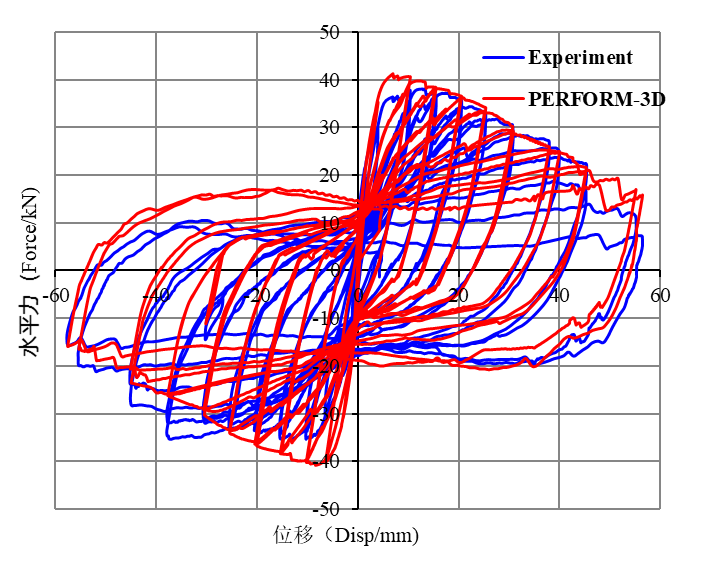
Most experts prefer solid elements, believing that solids should be more accurate. They also suggest that solid finite elements should consider the plasticity of reinforcement and the tensile and compressive damage of concrete. In fact, regarding the opinions of experts, we have no opportunity to refute them unless the experts themselves use Abaqus to perform solid element calculations. I respect all experts, so following their ideas is acceptable. However, the results may not necessarily meet the expectations of the experts. Below, I will use the cantilever column test results from文献[1] as an example to illustrate this point. Prior to this, I had obtained the following results using the fiber column elements in Perform3D. All parameters were determined based on test data and reasonable empirical parameters, with no artificial data fitting.
Figure | Comparison of Perform3D fiber section column results with test results
Later, I participated in a blind test competition for another frame structure using these parameter values and experiences, and I was awarded the second prize. This indicates that the parameters are relatively reasonable. Perform3D can achieve practical effects for beam and column elements.
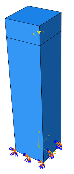
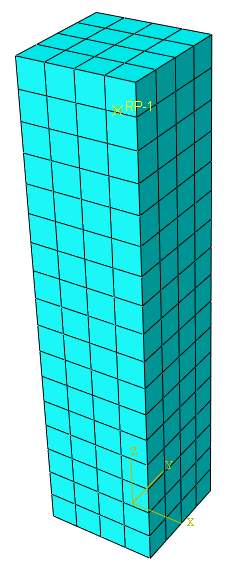
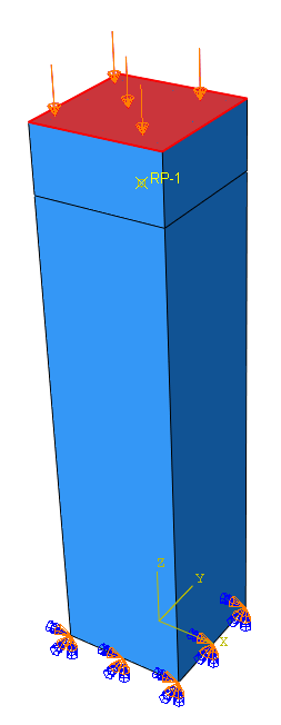
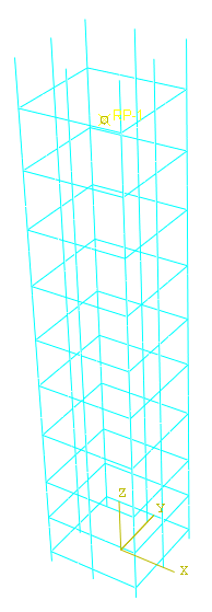
Figure
Abaqus solids, reinforcements, loads, and mesh
However, using Abaqus solid elements with ideal elastoplastic reinforcement and the built – in concrete damage constitutive (CDP) in Abaqus does not yield such ideal results. Although solid elements resemble the test specimens, their mechanical behavior is based on micro – scale materials, which is relatively complex and may make it difficult to simulate the ideal pinching effect.
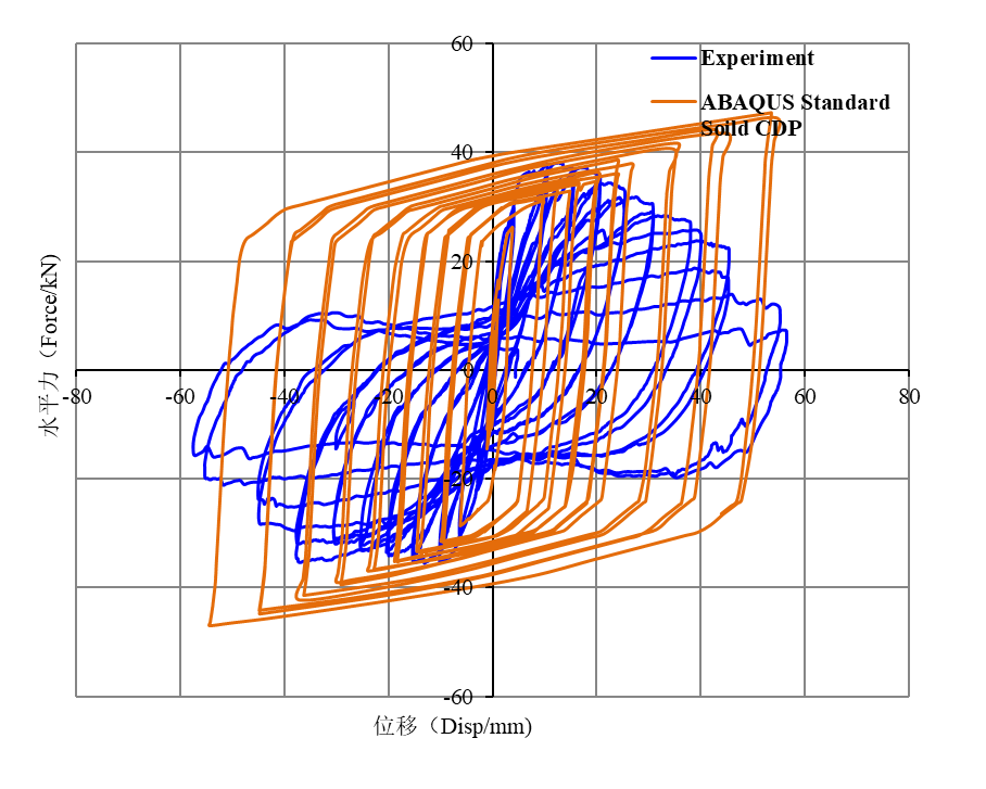
Figure | Comparison of Abaqus solid element results considering damage constitutive with test results
The pinching of this specimen is quite pronounced. Obviously, solid elements are not suitable for this task. However, a advantage of Abaqus is its flexibility, offering various elements and subroutines that allow users to customize their own material subroutines to meet their expectations. Of course, this must be based on reasonable parameters, and one should not unreasonably adjust parameters to achieve ideal results.
2 The Rationality of Abaqus Fiber Section Beam Elements
Abaqus fiber beam sections, combined with material subroutines, can generally yield relatively ideal results. Major design institutes and universities have developed their own subroutines, among which the relatively well – known material subroutine is PQFiber. It has been open – sourced and is available at www.qu – zhe.net/pqfiber.htm. For details, see文献[2]. Therefore, I also used PQFiber to run this test and obtained the following results.
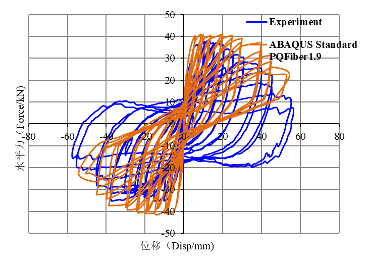
Figure | Comparison of Abaqus fiber beam element results using PQFiber1.9 with test results
显然,PQFiber can better account for the pinching effect. However, for more significant degradation effects, it may not be able to reasonably consider them (here, I used USTEEL02 and CONCRETE02 materials with default parameters, but it is possible that I have not yet found the appropriate parameters and further research is needed). Nevertheless, it is evident that the Abaqus fiber beam element in conjunction with PQFiber can yield relatively ideal results.
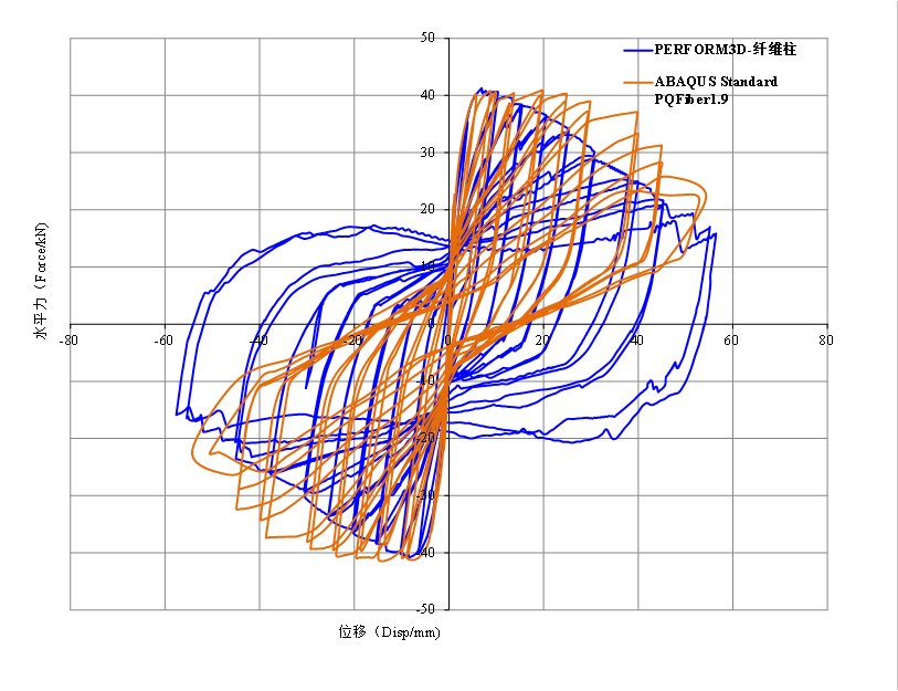
Figure | Comparison of Abaqus fiber beam element results using PQFiber1.9 with Perform3D fiber column results
The PQFiber fiber column and Perform3D fiber column can basically align well in the initial stage. However, adjustments may still be needed in the descending segment. In practical engineering, super – high – rise frame – core tube structures, frame – shear wall structures, and shear wall structures with a small number of frame columns rarely enter the degradation stage. Therefore, PQFiber can also achieve excellent results for general engineering applications and tests with less degradation.
3 Conclusion
The pinching effect is a significant characteristic in the hysteresis curves of reinforced concrete components, and currently, few elastoplastic software can accurately simulate it. Through the反复 push – over of a cantilever column, both Abaqus PQFiber and Perform3D can reasonably simulate this phenomenon. Although solid elements appear more realistic, the built – in concrete in Abaqus does not consider the hysteretic degradation effect, especially for reinforcement, making it difficult to simulate the pinching effect. However, they are more commonly used for monotonic push – over. In addition, by comparing the solid elements and fiber beam elements in Abaqus, it can be concluded that fiber beam elements with the PQFiber subroutine can better simulate pinching and degradation. Of course, this conclusion is drawn based on a single column, and more experiments can be conducted in the future to support it. Time is limited, so I will stop here today. Thank you to all friends for your attention, likes, and shares.
[Literature 1] Pseudostatic Collapse Test and Numerical Simulation Competition of Reinforced Concrete Frame Structures I Frame Test. Building Structure, 2012, 42(11): 19 – 22 + 26.
[Literature 2] Qu Zhe, Ye Lieping. 2011. A Bearing Capacity Degradation Model for Reinforced Concrete Components Based on Effective Cumulative Hysteretic Energy. Engineering Mechanics, 28(6): 45 – 51.